
CAUTION! Ingress of water will cause physical damage!
- Ensure that the cable entry and cable face downwards after installation.
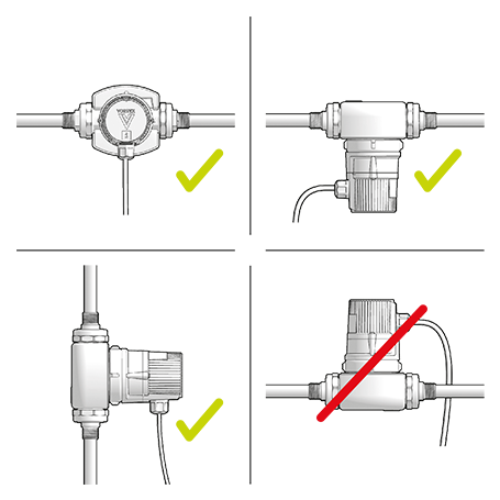
Select a suitable installation site and permissible installation position.
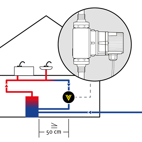
Avoid exposing pumps with thermostatic functions, such as the ERT or SL, to heat:
– Maintain a clearance of at least 50 cm from the DHW heater.
– If the return line opens vertically into the cylinder, install the pump well away from the cylinder entry.
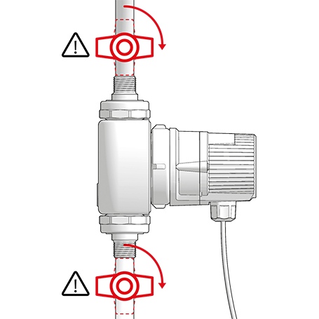
Fit shut-off valves and a non-return valve (Δpmax = 0.2 kPa or 20 mbar).
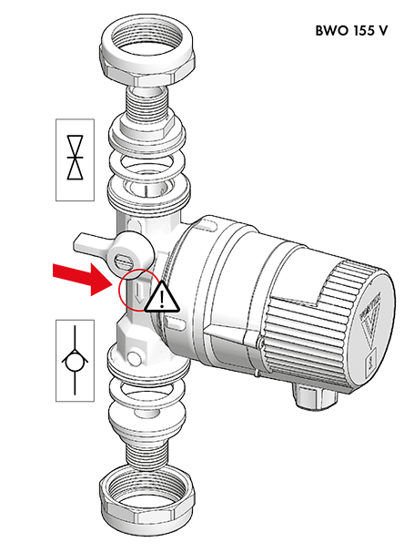
- The integrated shut-off valve in the V-pump housing and the Vortex screw-in valves are only provided to enable a brief shut-off while the motor is replaced.
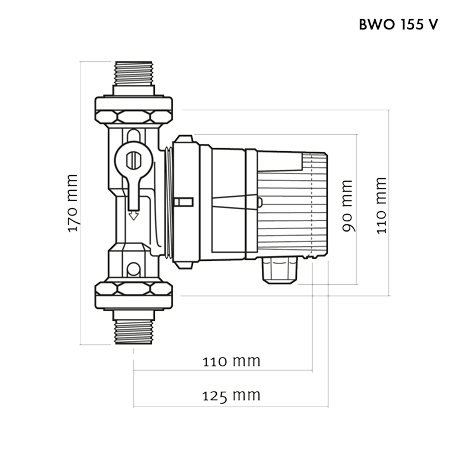
Integral valves on V pumps
Optional screw-in valves on R pumps (W-valves)
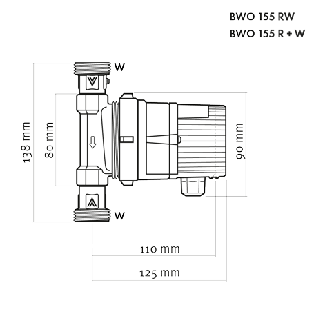
- Integral screw-in valves on BWO 155 RW pump
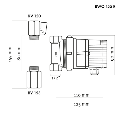
Optional screw-in valves on R pumps (RV 153, KV 150)
When installing the pump, ensure that it is not under strain.
- Observe correct direction of flow.

DANGER! Pressurised system!
- Before working on the motor or pump connections, close the shut-off valves.
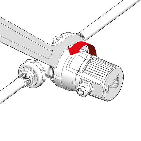
Rotate the pump control panel if necessary so that it is visible (cable exit underneath). To do so, slightly loosen the union nut …
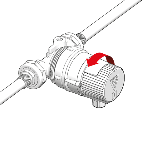
… turn the motor …
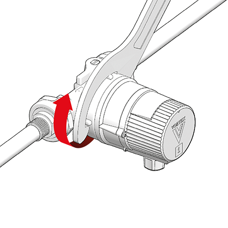
… and retighten the union nut (max. 20 Nm).
- Fully separating the motor from the pump housing is only necessary for maintenance purposes (see chapters ‘Flushing and venting’ and ‘Maintenance’).
- The pump has dry-running protection. If it runs largely in air, the PCB will repeatedly stop it to protect the rotor bearings. In a fully vented circulation circuit, the pump will run uninterrupted.