Safety
Product description
Included as standard
Specification
Installation
Flushing and venting
Electrical connection and setting the speed
Control module
Delivered condition
Setting the operating mode
Comfort settings
Restoring to delivered condition (resetting)
Functional description, self-learning module
Installation conditions
Installing the sensor cable and cable box
Maintenance and replacement
Faults and remedies
Disposal
EU Declaration of Conformity
Contact
These instructions apply to all specified product series and describe safe and appropriate use at all stages of operation.
Warnings and symbols

General safety information
- Installation, electrical connection and commissioning of the pump may be carried out only by qualified contractors and all general and local safety measures must be observed.
- Operating instructions and associated documents must be complete, legible and accessible at all times.
- Before carrying out work on the pump, read and ensure that you understand the operating instructions.
- This circulation pump is suitable only for water of potable quality.
- The pump should be operated only if it is in technically perfect condition. It must be used only in accordance with intended use, with an awareness of safety and risks, and in accordance with these instructions.
- Before any installation and maintenance work, disconnect the motor from the power supply and secure against reconnection.
- The use, cleaning and maintenance of this device by children aged 8 years or older, persons of restricted physical, sensory or mental capabilities, or persons with limited experience or knowledge is permitted only if they are supervised or instructed in the safe use of the device and understand the associated risks. Children must not be allowed to play with the device.
The BWO 155 BlueOne pumps are DHW circulation pumps driven by a high efficiency, electronically commuted DC motor. The are built on the original VORTEX spherical motor principle and contain a permanent magnet spherical motor.
The speed of the pump is infinitely adjustable.
The pump has LEDs and pushbuttons to display and set the operating state.
Operation
With the cable box installed on the flow line (see chapter ‘Installation conditions’), the pump operates as follows:
The self-learning module
- quickly and automatically learns the times when the users typically draw off DHW. Once it has learned these times, DHW provision is ensured predictively.
- automatically identifies variations from typical DHW usage, along with weekends, periods of absence and clock changes.
- has legionella protection functions (disinfection program detection1 and a daily circulation cycle of 15 minutes during absences of 24 hours or more).
- switches the pump off as soon as the PCB detects that hot water is available in the DHW circuit.
With the BWO 155 SL pump, pump run times can be reduced to a minimum. This does not contravene technical regulations, since the legionella protection required by these regulations is achieved by means of appropriate protective functions (see above). This is conditional on hygienically ideal installation and operation of the circulation system.
1 On condition that the DHW heater has a legionella function.
- Pump
- Flat gaskets and selected screw-connection set on pumps with V-pump housing
- Insulating shell for pump housing
- Quick operating guide
- Cable box with temperature sensor, 2.5 m sensor cable2 and releasable cable tie
- 3 cable ties for fixing the sensor cable
2 5 m sensor cable available as accessory
Max. delivery head
1,3 mWC
Max. pump rate
950 l/h
Electr. connection
1~115–230 V / 50–60 Hz
Power consumption
2,5–9 W
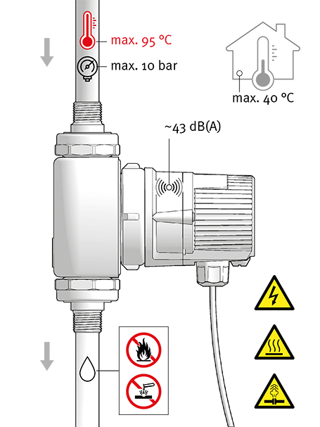
Media temperature
2–95 °C
IP rating
IP44
Permissible water hardness
Unrestricted
Dry-running protection
Yes

CAUTION! Ingress of water will cause physical damage!
- Ensure that the cable entry and cable face downwards after installation.
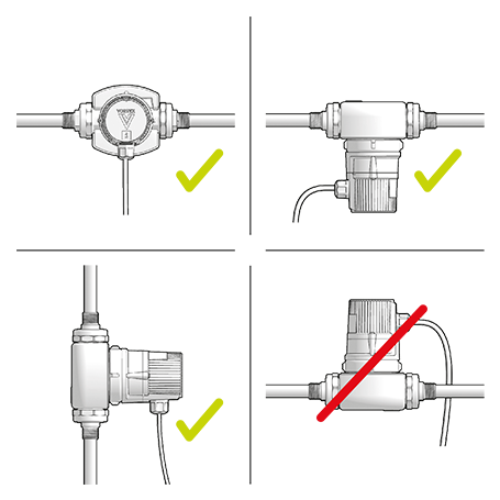
Select a suitable installation site and permissible installation position.
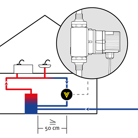
Avoid exposing pumps with thermostatic functions, such as the ERT or SL, to heat:
– Maintain a clearance of at least 50 cm from the DHW heater.
– If the return line opens vertically into the cylinder, install the pump well away from the cylinder entry.
Fit shut-off valves and a non-return valve (Δpmax = 0.2 kPa or 20 mbar).
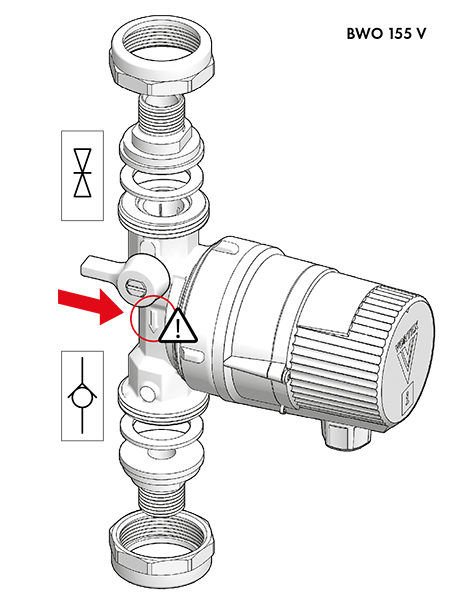
- The integrated shut-off valve in the V-pump housing and the Vortex screw-in valves are only provided to enable a brief shut-off while the motor is replaced.
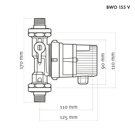
Integral valves on V pumps
Optional screw-in valves on R pumps (W-valves)
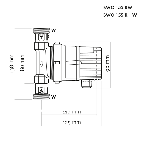
- Integral screw-in valves on BWO 155 RW pump
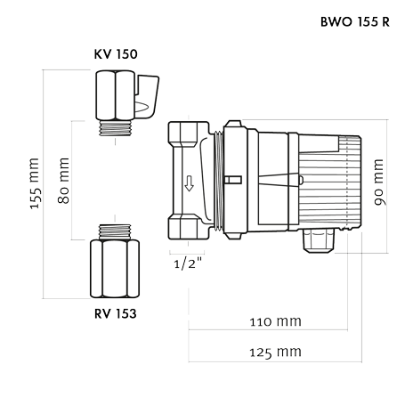
Optional screw-in valves on R pumps (RV 153, KV 150)
When installing the pump, ensure that it is not under strain.
- Observe correct direction of flow.

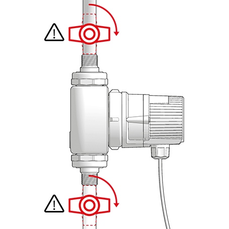
DANGER! Pressurised system!
- Before working on the motor or pump connections, close the shut-off valves.
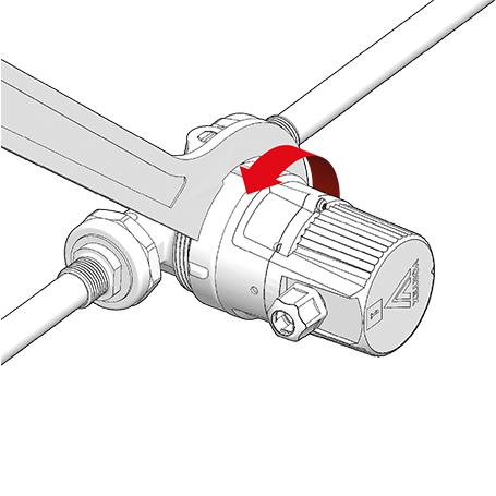
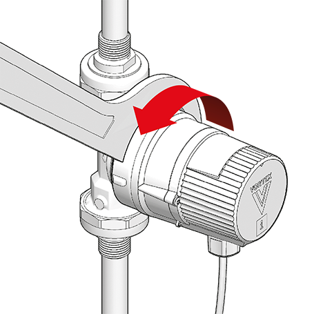
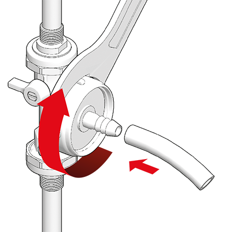
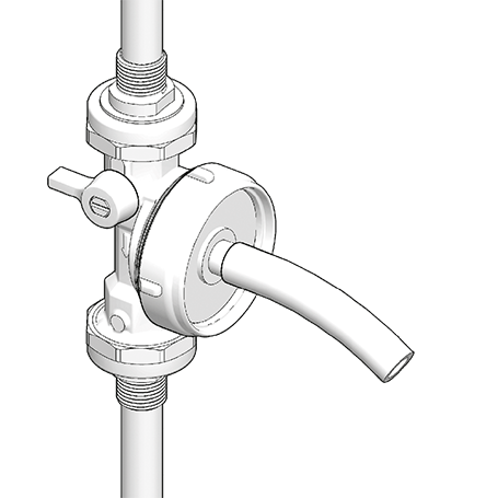
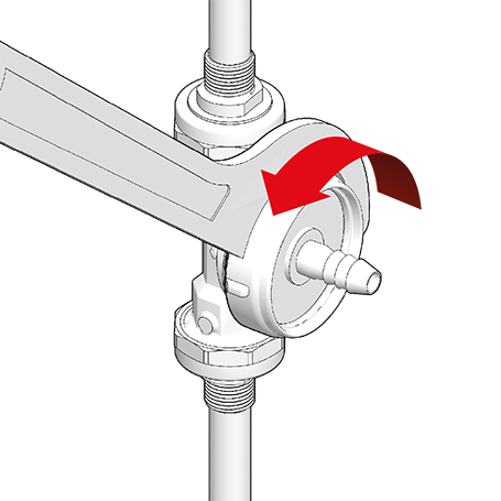
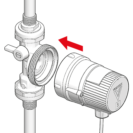
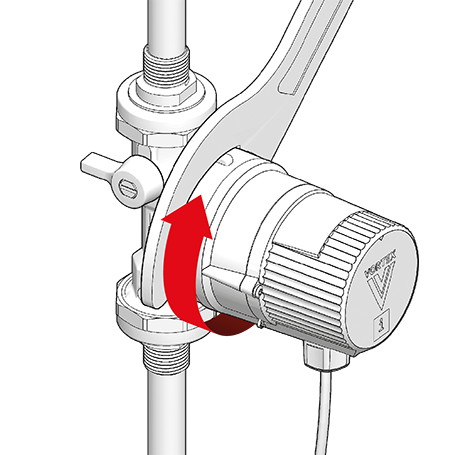
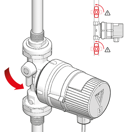
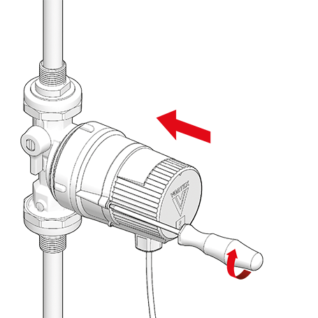
Rotate the pump control panel if necessary so that it is visible (cable exit underneath). To do so, slightly loosen the union nut …
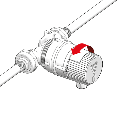
… turn the motor …
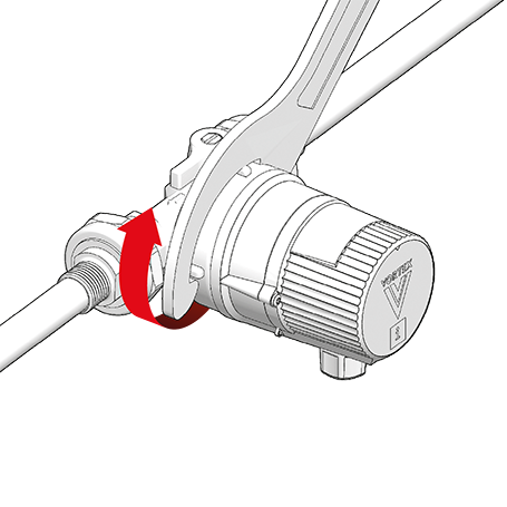
… and retighten the union nut (max. 20 Nm).
- Fully separating the motor from the pump housing is only necessary for maintenance purposes (see chapters ‘Flushing and venting’ and ‘Maintenance’).
- The pump has dry-running protection. If it runs largely in air, the PCB will repeatedly stop it to protect the rotor bearings. In a fully vented circulation circuit, the pump will run uninterrupted.
CAUTION! Dry-running will damage the bearings!
- Flush the pipework thoroughly with water and vent it.
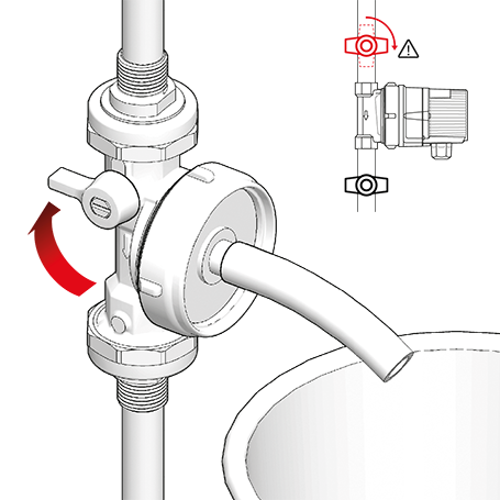
DANGER! Pressurised system!
- Before working on the motor or pump connections, close the shut-off valves.

WARNING! Risk of scalding due to hot water!
- Avoid direct contact with escaping hot water.
- The pump housing can similarly reach a high temperature due to the hot medium being pumped.
- If no venting valve (fill & drain valve) is present, the system must be vented through the pump housing.
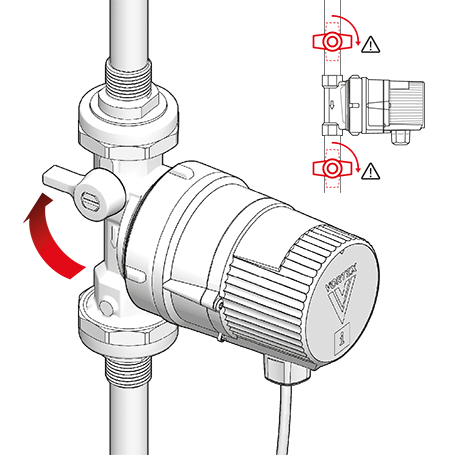
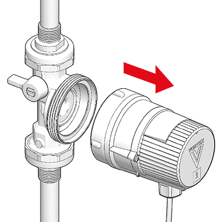
To vent, first close the shut-off valves.
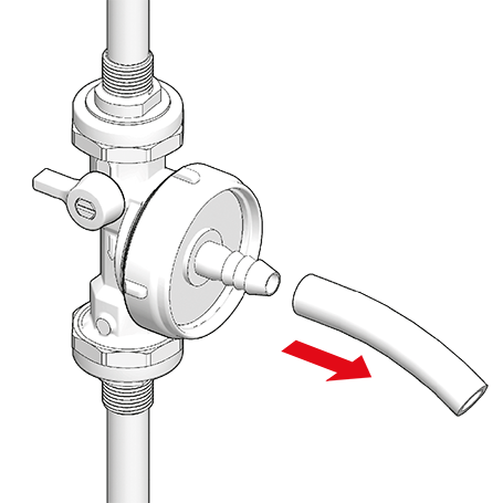
Unscrew the motor from the pump housing …
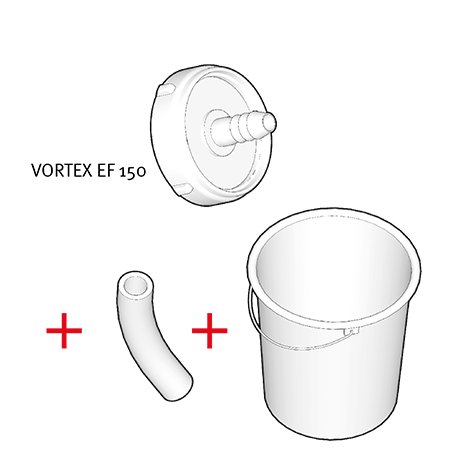
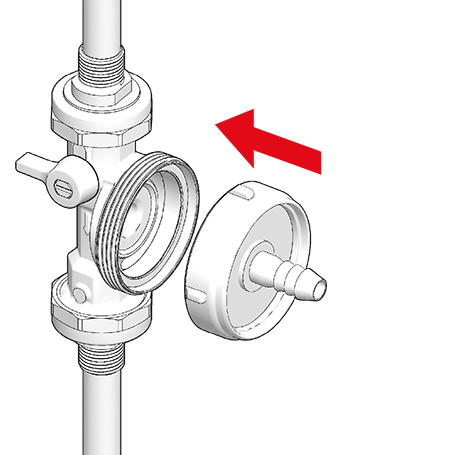
… and screw the venting flange (VORTEX EF 150) onto the motor (max. 20 Nm).
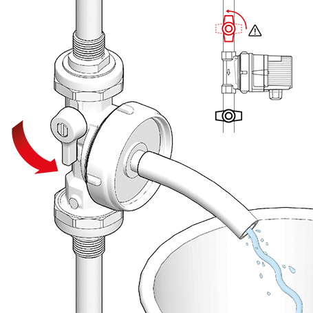
Open the shut-off valve upstream of the pump again and allow water to escape through the venting flange until the pipework is free of air.
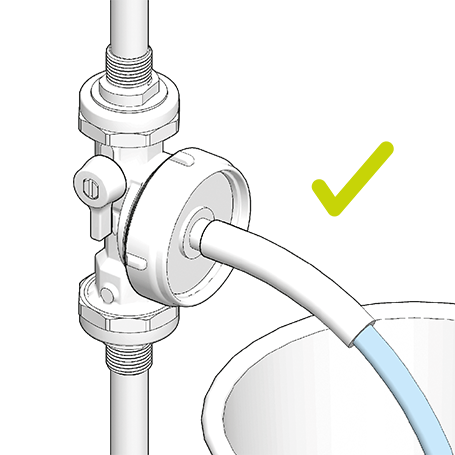
Close the shut-off valve upstream of the pump …
… unscrew the venting flange from the pump …
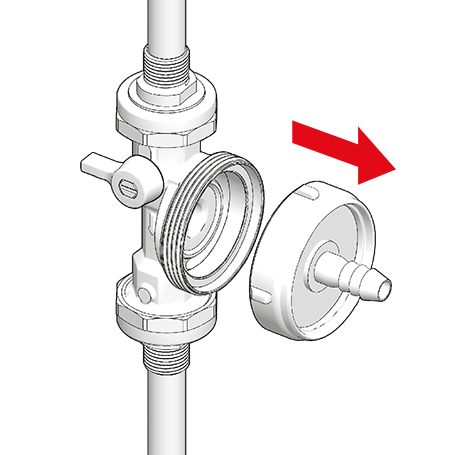
… and reattach the motor to the pump housing.
Retighten the union nut (max. 20 Nm).
Slowly open the shut-off valves again.
- The pump is driven by a DC motor.
- The transformer for AC operation is built into the connection cap.
- As it is in protection class 2, no earth conductor is required.

DANGER! Electric shock can kill!
- Work on the electrics must be carried out only by authorised contractors.
- Disconnect the pump from the power supply and secure against reconnection.
- Check that no voltage is present.
WARNING! Risk of fire due to electrical ignition!
- Ensure that the pump is connected only to the power supply specified on the type plate.
- A permanent connection to the power supply is possible; alternatively use a mains plug with IP 44 rating (provide all-pole disconnection).
- Round cable diameter 5–8 mm
- Wire cross-section 0.75–1.5 mm2
- Strip 8.5–10 mm of insulator from the ends of the wires.
- Twist the wire ends; do not use wire-end sleeves or tinned ends.
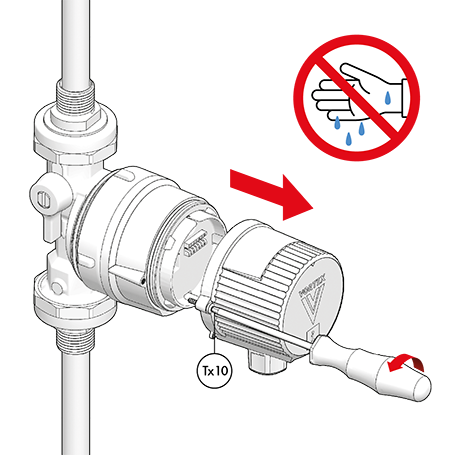
Undo the module cap with a TX10 screwdriver.
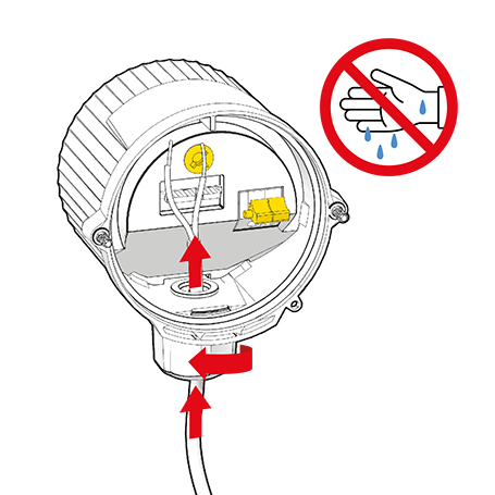
Undo the cap nut and insert the cable.
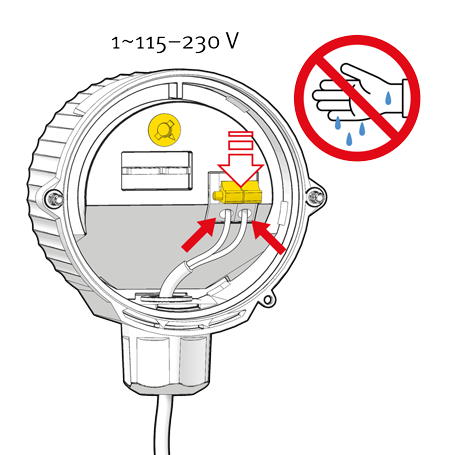
Push yellow lever forward and insert the wire into the red cable terminal. Release the lever again.
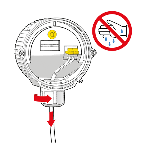
Allow a suitable length of cable and retighten the cap nut.
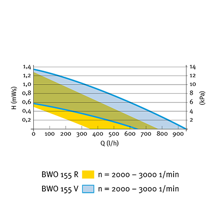
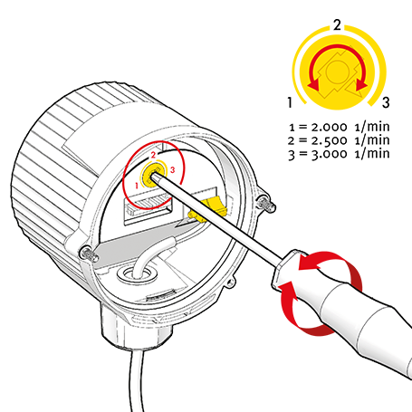
Adjust speed by turning the rotating yellow knob:
1 = min. speed (2000 rpm)
2 = medium speed (2500 rpm = factory setting)
3 = max. speed (3000 rpm), or use any intermediate position.
Screw the module cap on firmly.
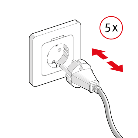
To vent any remaining air, switch the pump on and off several times …
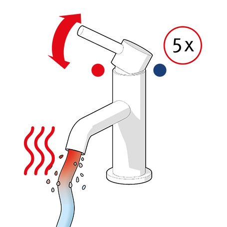
… and open the DHW tap several times …
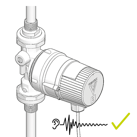
… until the pump runs quietly.


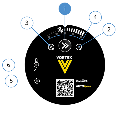
(1) ‘Continue’ button
(2) LED indicator: Pump continuously on
(3) LED indicator: Pump permanently off
(4) LED indicator: Comfort setting
(5) LED indicator: Pump monitor (LED green = pump ON) (LED not lit = pump OFF)
(6) LED indicator: Sensor cable connection (LED red = not connected) (LED not lit = connected)
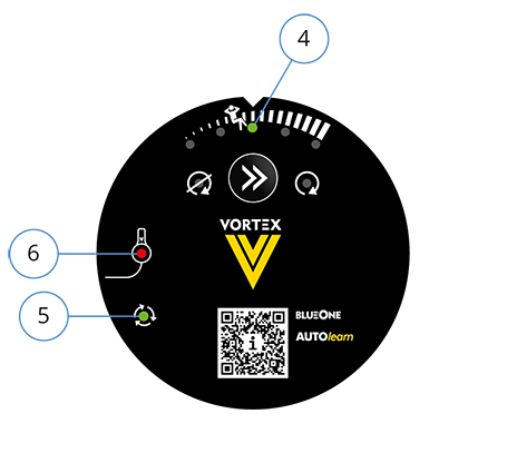
- The cable box with the sensor cable is attached to the module cap (with a retaining thread which should not be removed until the cable box is to be installed). The sensor cable is already factory-fitted to the module.
- Unless the sensor cable is connected to the cable box, the pump runs continuously. The LED indicator for sensor cable connection (6) glows red (when the sensor cable is connected, it goes out).
- The LED indicators for pump control (5) and comfort setting (4) stage 3 glow green.
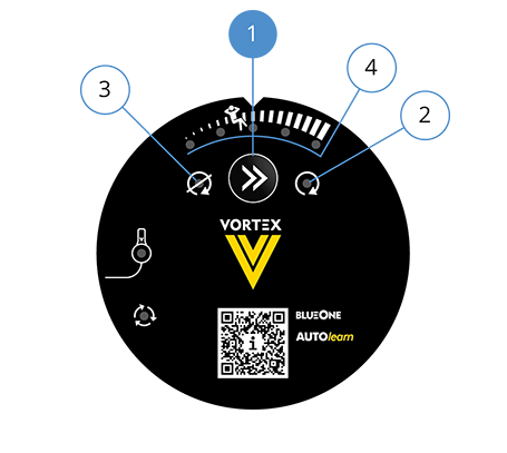
Press the ‘Continue’ button (1) repeatedly until the relevant LED glows green:
– Comfort setting with 5 stages (4) (see chapter ‘Comfort settings’)
– Pump in continuous operation (2)
– Pump permanently off (3)
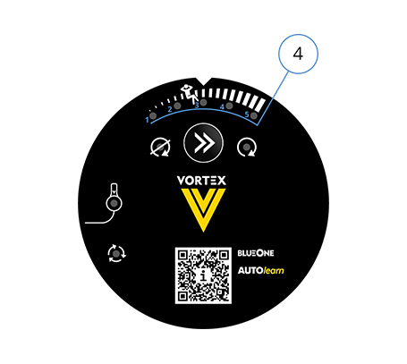
LED indicator: Comfort setting (4)
Left to right:
- Stage 1: Maximum energy saving; pump runs on demand
- Stage 2: Standard comfort; pump runs at regular draw-off times
- Stage 3: Default setting; good level of comfort; total runtime approx. 2–3 hours/day. This stage is the best for most applications. We recommend not changing the comfort setting until at least three weeks have passed.
- Stage 4: Very high level of comfort; pump runs more frequently each day
- Stage 5: Maximum comfort; pump runs even at irregular draw-off times; total runtime up to 5 hours/day

- Press and hold the ‘Continue’ button (1) for 5 seconds. All learnt switching commands are deleted and Comfort setting 3 is set.
or
- Switch off the power supply to the pump. All learnt switching commands are deleted but the previously set Comfort setting is retained.
- How does the pump learn?
A DHW tap is turned on. The flow line heats up. The pump identifies this from the external temperature sensor and learns the time at which DHW is drawn.
- When does the pump start running?
During the learning phase (for 2 weeks after commissioning) the pump starts relatively frequently and independently of when DHW is drawn off. This ensures convenience in the first weeks after installation. After the learning phase, the pump starts up in the following circumstances:
– predictively (at the typical learnt times),
– immediately when DHW is drawn off (at times that have not yet been learnt), unless the flow line is already heated,
– for a flushing or disinfection run (see below). The pump determines the need to run for each individual day (Monday to Sunday), on the basis of DHW usage in the past 2 weeks.
- How long does the pump run?
The pump runs for as long as necessary to supply the DHW circuit with hot water (determined via the thermostat in the pump). The runtime depends on the size of the circulation system.
- For how long each day does the pump run?
The daily runtime depends on the size of the circulation system, the comfort setting and on users’ DHW draw-off patterns. Generally, the pump runs for between 1 and 5 hours a day.
- How does the disinfection program detection work?
The highest flow temperature measured over the course of a week is interpreted as the disinfection run temperature. At this time the pump then runs for 30 minutes (once a week). If a higher flow temperature is detected at a different point in the week, the pump controller shifts the disinfection run to this time.
- How is a period of absence detected (holiday detection)?
If no DHW is drawn for 24 hours, the pump switches to absence. Predictive pump runs will then no longer take place. A 30-minute disinfection run, however, will continue to take place (once a week). Other than this, the pump operates a flushing run once a day (duration: 15 minutes).
- How is a return from a period of absence detected?
If DHW is drawn off twice in the space of an hour, the previously learnt pattern is then restored.
- The cable box should be installed on the DHW flow (regardless of the type of DHW heating system).
- The optimum distance from the cable box to the DHW heater is 20–30 cm (for a plastic/composite pipe) or 50 cm (for a metal pipe).
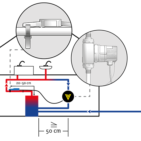
- If the flow line exits vertically from the DHW heater, fit a U-bend upstream of the sensor installation location. Otherwise DHW draw-off will not be detected as the temperature change will be too small.
- If a mixer tap is installed, install the cable box at an appropriate distance downstream of the mixer tap.
- Install the cable box only on a straight section of pipe (without bends, corrugations, taps or tee-joints).
- The DHW heating system must deliver a constant temperature level of at least 50 °C (except during night setback), in accordance with the technical regulations. Otherwise the required level of DHW convenience cannot be guaranteed.
- Branched pipework systems (multiple-circuit systems) must be hydraulically balanced by means of regulating valves in the return lines. Otherwise the level of convenience may be adversely affected as the pump may switch off too early.
Notes
- The pump requires a permanent power supply.
- Do not connect the pump to an additional controller or timer.
- If the power supply is interrupted
– all learnt switching commands are deleted,
– the previously set operating state is retained.
- If hot water is not available directly after opening a tap, turn the tap off again and wait for circulation to start.
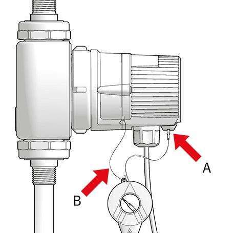
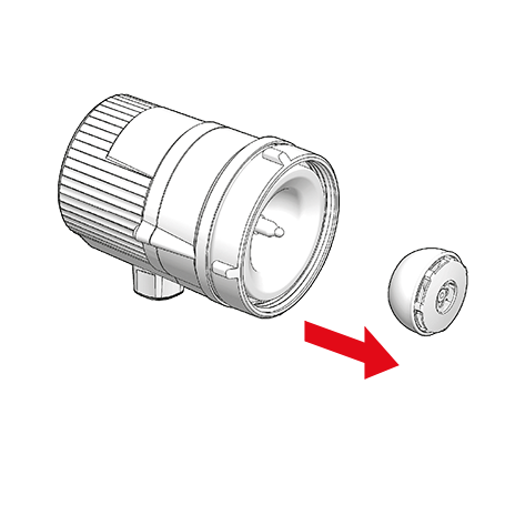
- The sensor cable is already factory-fitted to the module (A).
- If the sensor cable is pulled out, it can be reconnected to the module. Carefully reinsert the blue cable plug into the rubber sleeve (A) on the module.
- Do not cut the retaining thread (B) between the cable box and the module cap until the cable box is to be installed.
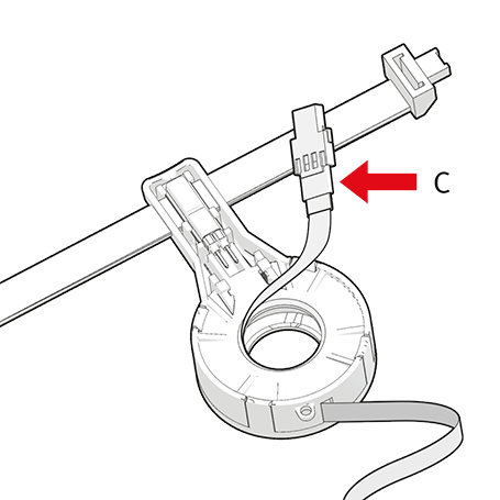
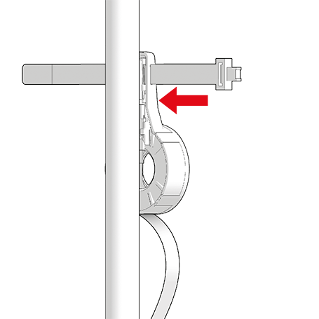
- Determine the distance from the pump to the installation position of the cable box. Do not pull the sensor cable further out of the cable box than is absolutely necessary. The maximum length of the sensor cable is 2.5 m. A 5 m sensor cable is available as an accessory.
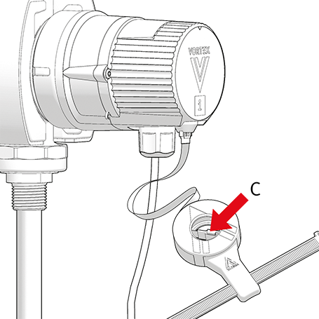
Note:
The sensor cable can be unwound only as long as the plug on the other end of the sensor cable (C) has not yet been plugged into the contact pins on the sensor.
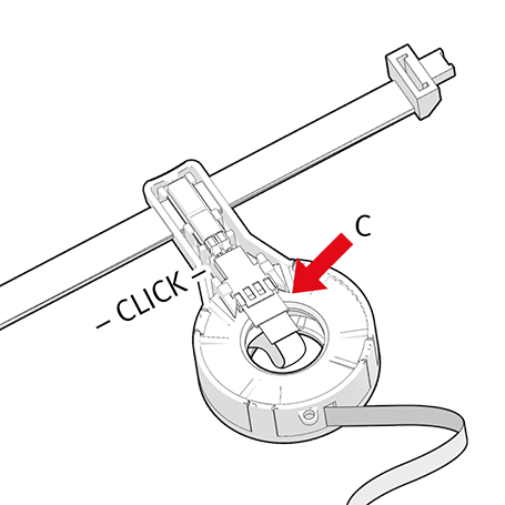
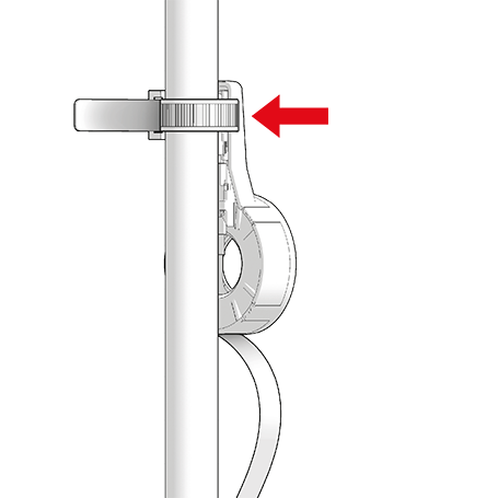
Once the sensor cable has been unwound, slide plug (C) onto the two contact pins on the sensor so that the retaining lugs on the left and right click into place.
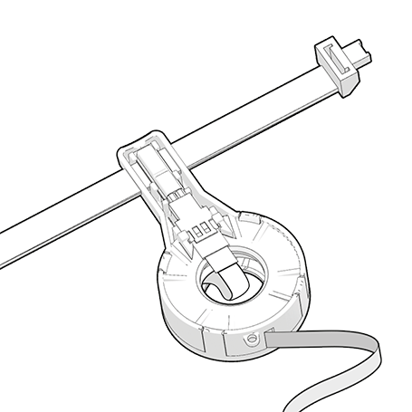
Secure the cable box to the DHW flow line only using the integral cable tie.
Ensure good contact between the sensor and the DHW flow line (do not use any additional materials such as thermal paste!).
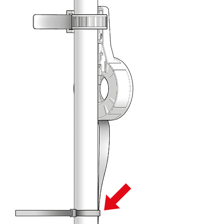
- Do not exert mechanical strain on the cable box (do not enclose in insulation!).
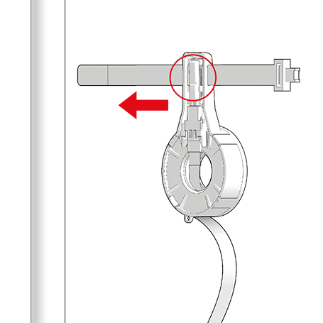
WARNING! Loose sensor cable is a trip hazard.
- After fitting the sensor cable, secure it with cable ties (supplied).
- The pump and self-learning module are now ready for operation. When the power supply is connected, the LED for Comfort setting 3 (default setting) lights up. The pump starts and the learning process begins.
DANGER! Electric shock can kill!
- Before working on the pump, disconnect from the power supply and secure against reconnection.
- Check that no voltage is present.
DANGER! Pressurised system!
- Before working on the motor or pump connections, close the shut-off valves.
WARNING! Risk of scalding due to hot water!
- Avoid direct contact with escaping hot water.
- The pump housing can similarly reach a high temperature due to the hot medium being pumped.
- Whenever the motor is opened up, replace the seal in the pump housing.
For maintenance, first close the shut-off valves.
Unscrew the motor from the pump housing …
… Carefully lift the rotor off the bearing pin.
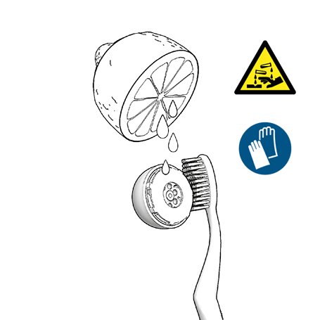
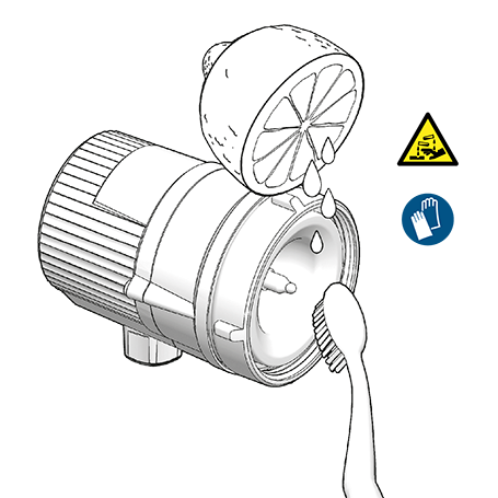
Using a limescale remover, free the rotor and separating cap of limescale. If necessary, replace the rotor. Use only soft, non-metallic tools (e.g. brush, cloth, toothpick).
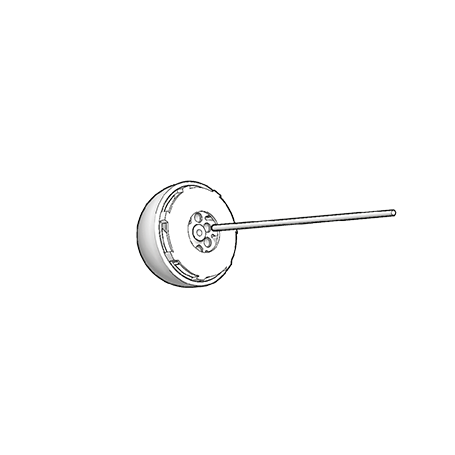
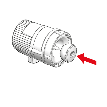
Reposition the rotor on the bearing pin.
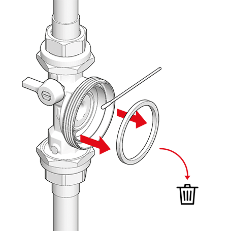
Remove the old seal.
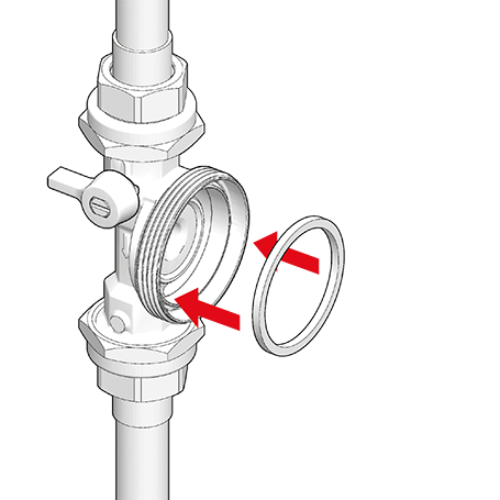
Insert new seal into the pump housing …
… and reattach the motor to the pump housing.
Retighten the union nut (max. 20 Nm).
Slowly open the shut-off valves again.
To vent any remaining air, switch the pump on and off several times …
… and open the DHW tap several times …
… until the pump runs quietly.


This symbol on the product or packaging means that the product must be put into a separate facility for electrical and electronic devices and not disposed of in regular household waste. By disposing of it correctly you will be helping to avoid negative effects to the environment and to human health that may arise from incorrect allocation and handling of old electrical goods.
For further information, please contact your local authority, the waste disposal organisation or the company from which you obtained the product.
This product complies with the applicable European directives and corresponding national regulations and standards.
 272 KB
Deutsche Vortex GmbH & Co. KG
Kästnerstr. 6
71642 Ludwigsburg
Head office
Phone +49 (0) 71 41 / 25 52-0
Fax: +49 (0) 71 41 / 25 52-70
Email: