Safety
Product description
Scope of delivery
Technical specifications
Installation
Flushing and venting
Electrical connection
Maintenance and replacement
Faults and remedies
Disposal
EU Declaration of Conformity
Contact
Legally binding language
These instructions are valid for all series named. They describe how to use the product safely and correctly during all operating phases.
Warning labels and symbols

General safety instructions
- Installation of pump must be performed by qualified personnel only.
- Keep the operating instructions and other applicable documents complete, in a legible condition and permanently accessible.
- Read the operating instructions and make sure you understand them before working on the pump.
- This circulator is suitable for drinking water only.
- Only operate the pump if it is in perfect technical condition; only use it as intended, staying aware of safety and risks, and adhering to the instructions in this manual.
- Before carrying out any installation or maintenance work, disconnect motor from power supply and ensure it cannot be reconnected unintentionally.
- This device can be used, cleaned or maintained by children aged from 8 years, by persons with limited physical, sensory or mental faculties as well as by persons with limited experience or lack of knowledge if they are under supervision or after they have been instructed for the safe use of the device and understand the resulting dangers. Children must not play with the device.
The BlueOne pump BWO 200 is a domestic hot water pump with a highly-efficient electronically commutated DC motor as drive source. It is built according to the original VORTEX spherical motor principle and contains a permanent magnetic rotor.
The BlueOne pump BWO 200 is suitable for compact pipe systems requiring an increased delivery flow (e.g. when having bigger pipe diameters).
- Pump
- Insulating cover for pump housing
- 2 gaskets
- Quick-Guide
Max. delivery head
1,3 mWS
Max. flow rate
1.500 l/h
Electr. connection
1~230 V / 50 Hz
Max. power consumption
12 W
Average power consumption
9,5 W
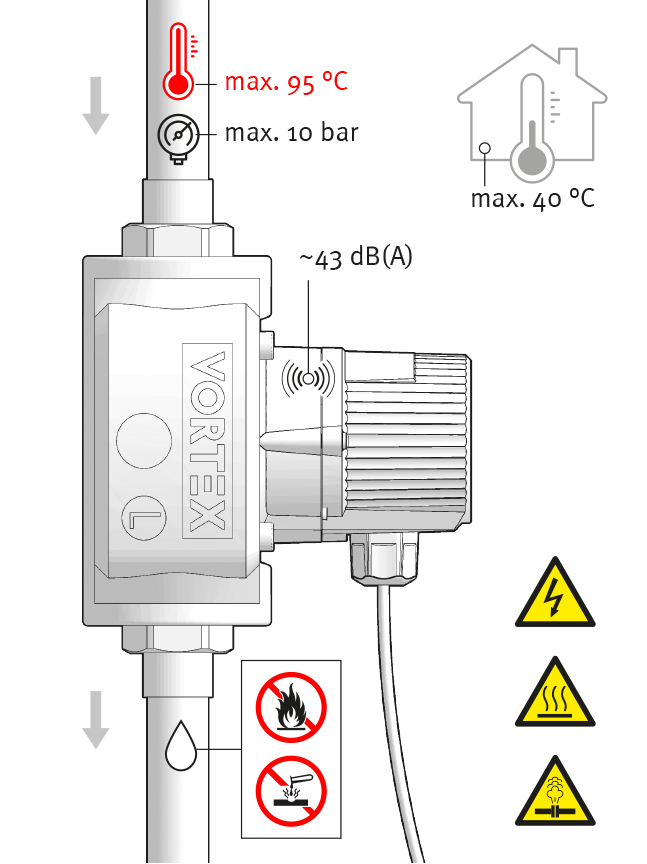
Max. fluid temperature
2–95 °C
IP rating
IP44
Permissible water hardness
Unlimited
Dry-running protection
Yes
Centre distance
140 mm
Thread connection
1" (external)

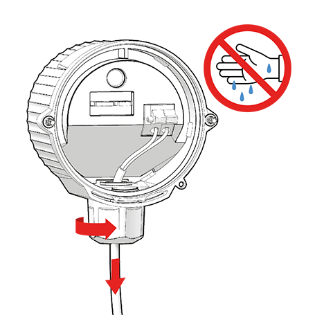
Careful! Ingress of water will cause physical damage!
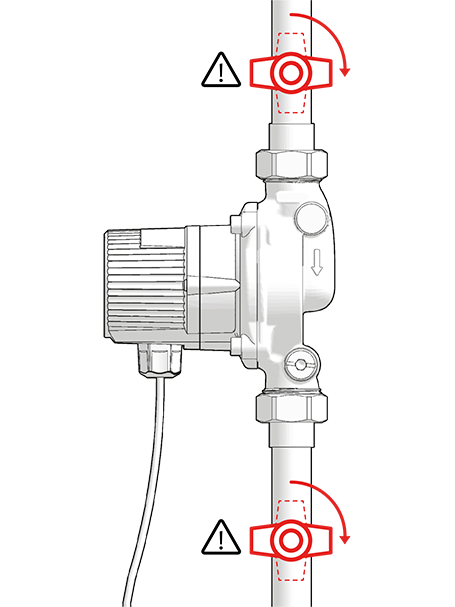
- Ensure that the cable entry and cable face downwards after installation.
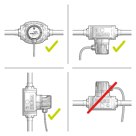
Select a suitable installation site and permissible installation position.
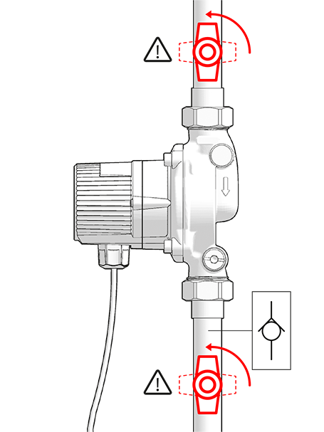
Make sure, that isolation valves and a check-valve (∆pmax = 0,2 kPa or 20mbar) are mounted.
- When installing the pump, ensure that it is not under strain.
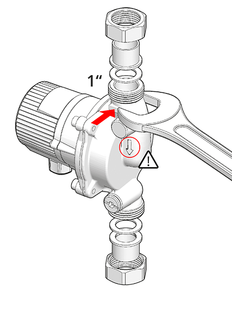
Look out for correct flow direction.

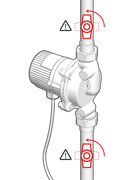
Danger! Pressurised system!
- Before working on the motor or pump connections, close the shut-off valves.
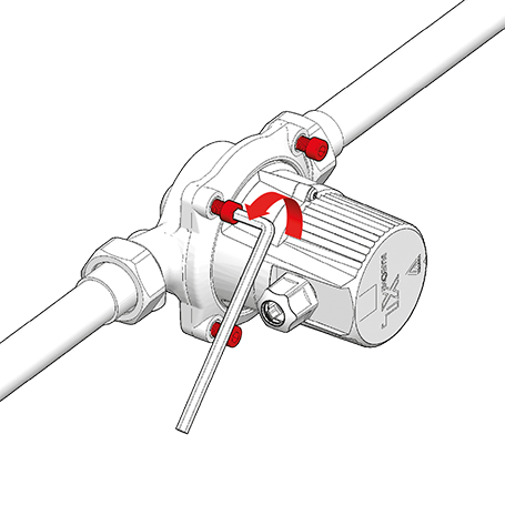
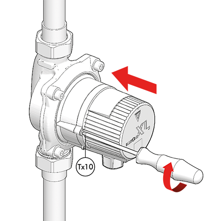
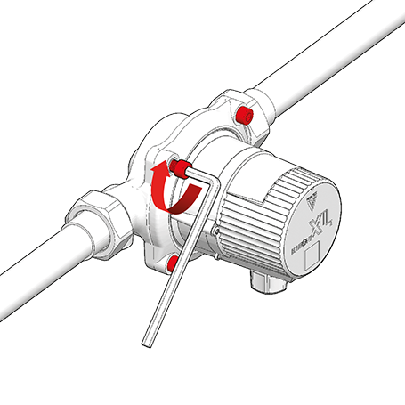
For turning the pump motor (cable outlet should show downwards) loosen M6-screws, …
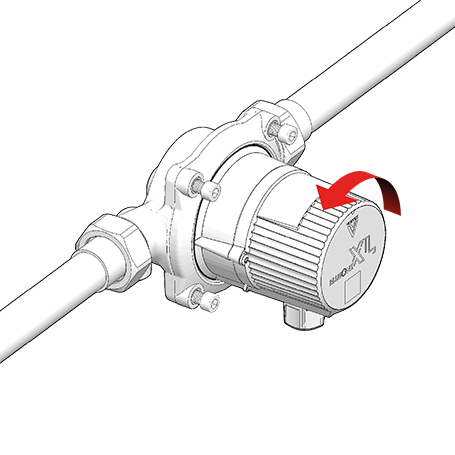
… turn the pump motor, …
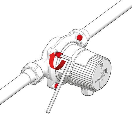
… then tighten the screws again
(max. 5 Nm).
- Fully separating the motor from the pump housing is only necessary for maintenance purposes (see chapters ‘Flushing and venting’ and ‘Maintenance’).
- The pump has dry-running protection. A lack of water in the pump housing is recognised immediately by the pump electronics. Rotor run will be interrupted in order to avoid early wear of the rotor bearing. In a fully vented circulation circuit, the pump will run uninterrupted.
Careful! Dry-running will damage the bearings!
- Flush pipework thoroughly with water and vent it.
Beforehand:
- Disconnect the pump from the power supply and secure against reconnection.
- Check that no voltage is present.
Danger! Pressurised system!
- Before working on the motor or pump connections, close the shut-off valves.

Warning! Risk of scalding due to hot water!
- Avoid direct contact with escaping hot water.
- The pump housing can similarly reach a high temperature due to the hot medium being pumped.
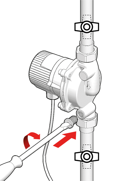
To vent, first close the isolation valves.
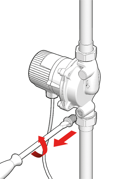
Unscrew bleeder screw completely …
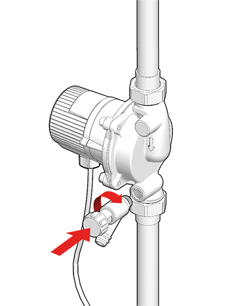
… and fix a usual drain valve with ¼“-thread connection.
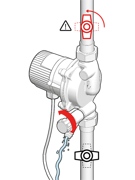
Open isolation valve in front of pump inlet and vent pump by opening the drain valve. Make sure, that return line gets completely vented.
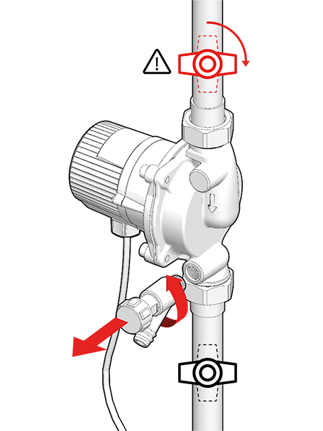
Close isolation valve in front of pump inlet, unscrew drain valve, …
… and remount bleeder screw to pump housing.
Slowly open the isolation valves again.
- The drive of the pump is a DC motor.
- For AC operation a transformer is integrated in the module cap.
- Due to protection class 2 a protective conductor (ground wire) is not required.

Danger! Danger of electrocution!
- Have all electrical work carried out by qualified personnel only.
- Disconnect motor from power supply and ensure it cannot be reconnected unintentionally.
- Check if pump is de-energized.
Warning! Fire hazard due to electrical ignition!
- Make sure that the pump is only connected to the power supply specified on the name plate.
- A permanent power supply is possible, alternatively use a mains plug with IP 44 rating (provide isolator that separates all poles).
- Round cable diameter 5 – 8 mm
- Cord diameter 0.75 – 1.5 mm2
- Strip cords by 8.5 – 10 mm.
- Twist wires (no wire end sleeves, no tinned ends).
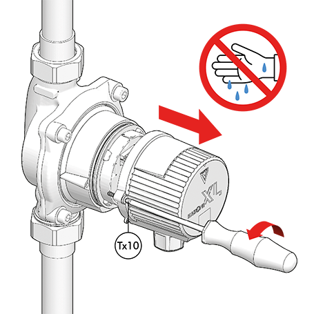
Undo module cap with a Tx10 screwdriver.
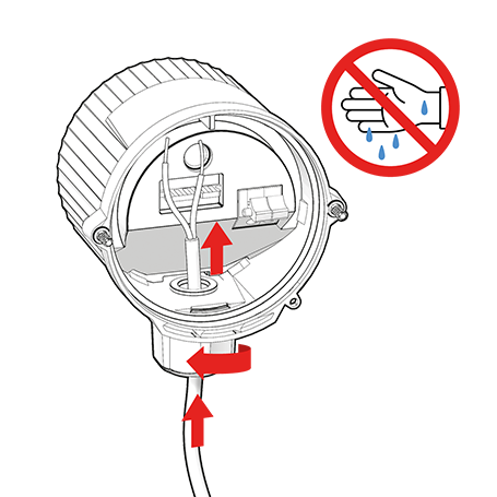
Loosen the cap nut and insert cable.
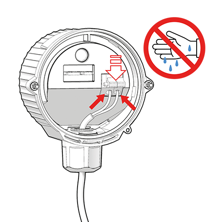
Push forward the yellow lever, insert cable wires into red clamp, then release the yellow lever again.
Arrange the cable properly inside the module cap, then refasten the cap nut.
Refasten the module cap.
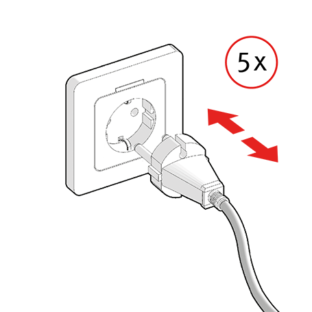
For final venting alternately turn the pump on and off …
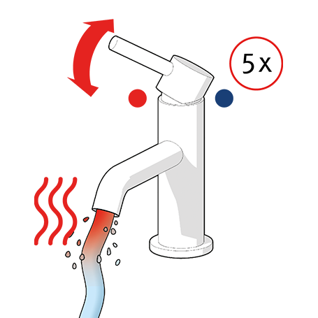
… and open and close hot water tap several times …
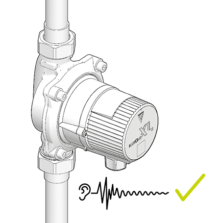
… until noiseless pump run is achieved.
Danger! Electric shock can kill!
- Before working on the pump, disconnect from the power supply and secure against reconnection.
- Check that no voltage is present.
Danger! Pressurised system!
- Before working on the motor or pump connections, close the shut-off valves.
Warning! Risk of scalding due to hot water!
- Avoid direct contact with escaping hot water.
- The pump housing can similarly reach a high temperature due to the hot medium being pumped.
- Whenever the motor is opened up, replace the seal in the pump housing.
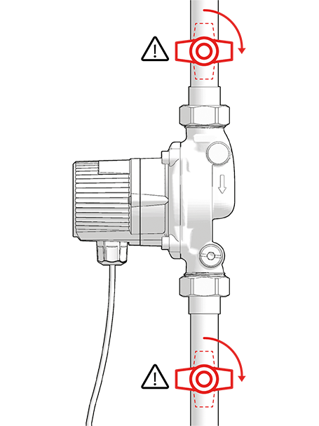
For maintenance, first close the isolation valves.

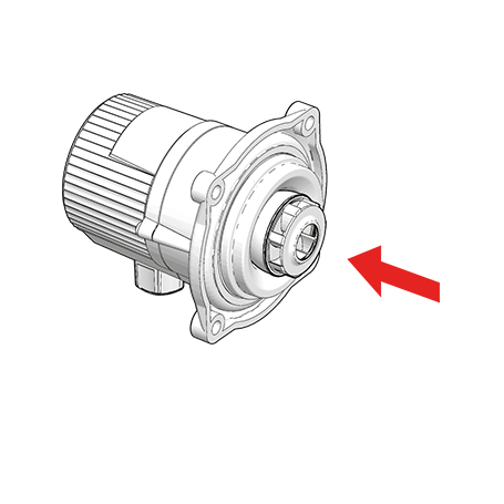
Demount M6-screws completely.
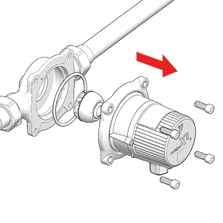
Remove pump motor.
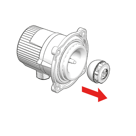
Carefully lift the rotor off the bearing pin.
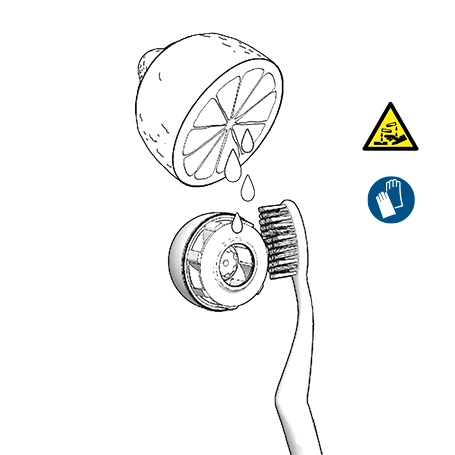
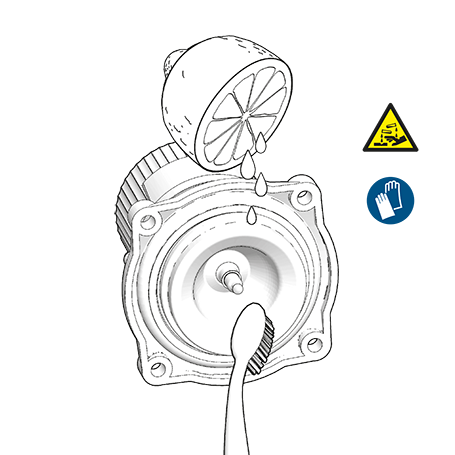
Using a limescale remover, free the rotor and separating cap of limescale. If necessary, replace the rotor. Use only soft, non-metallic tools (e.g. brush, cloth, toothpick).
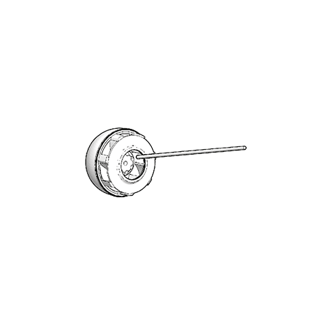
Reposition the rotor on the bearing pin.
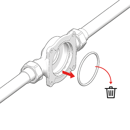
Dispose of used O-ring.
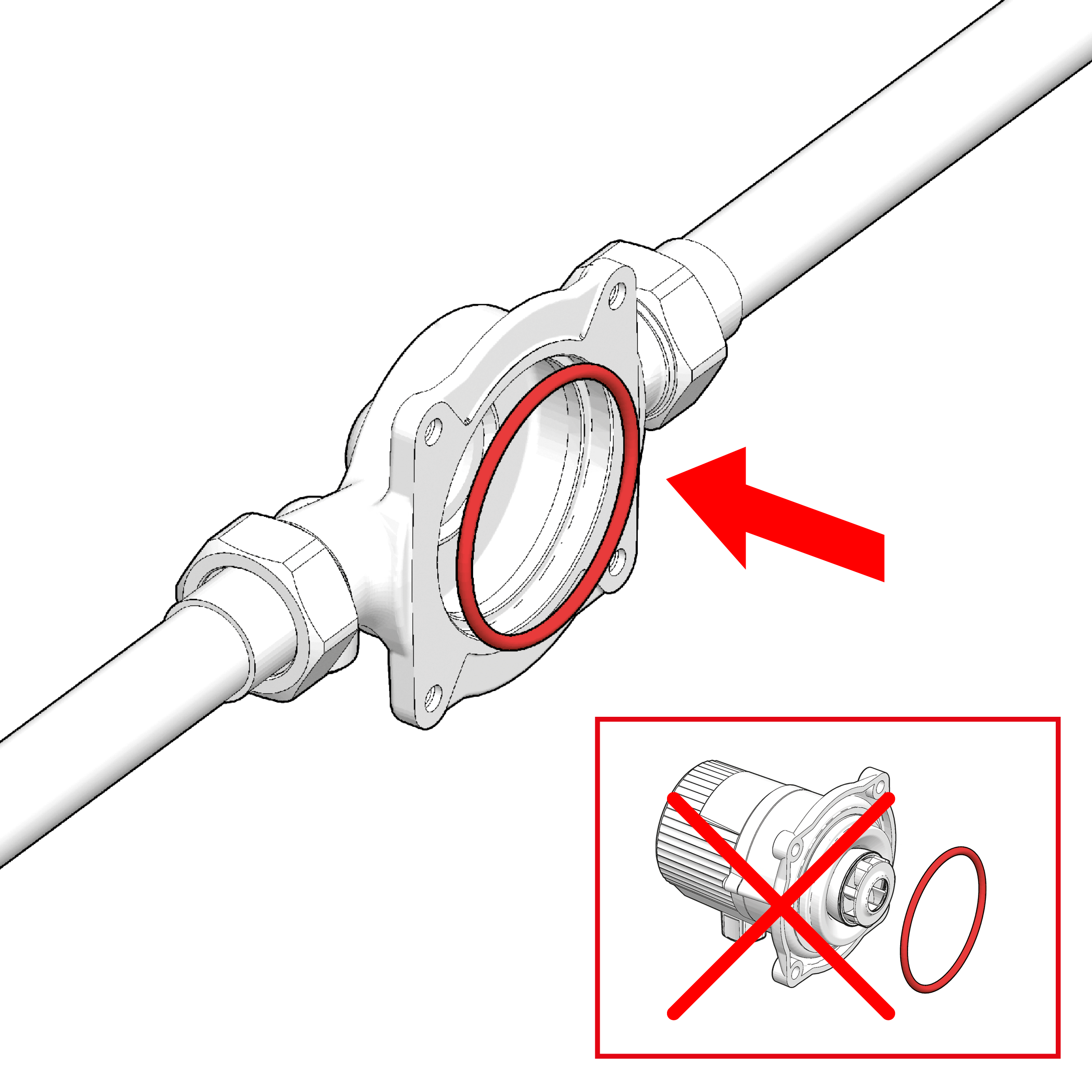
Insert new O-ring into the pump housing and press slightly into place.
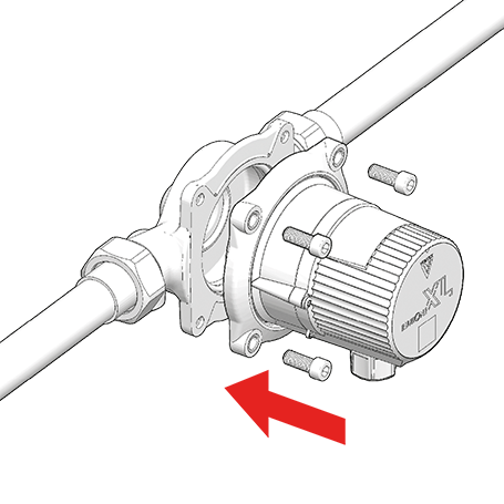
Remount pump motor.
Tighten M6-screws
(max. 5 Nm).
Slowly open the shut-off valves again.
To vent any remaining air, switch the pump on and off several times …
… and open the DHW tap several times …
… until the pump runs quietly.


This symbol on the product or packaging means that the product must be put into a separate facility for electrical and electronic devices and not disposed of in regular household waste. By disposing of it correctly you will be helping to avoid negative effects to the environment and to human health that may arise from incorrect allocation and handling of old electrical goods.
For further information, please contact your local authority, the waste disposal organisation or the company from which you obtained the product.
This product complies with the applicable European directives and corresponding national regulations and standards.
 272 KB
Deutsche Vortex GmbH & Co. KG
Kästnerstr. 6
71642 Ludwigsburg
Germany
Head Office
Phone: +49 (0) 71 41 / 25 52-0
Fax: +49 (0) 71 41 / 25 52-70
E-mail:
Legal Information Data Privacy
The original operating manual is written in German. This version is legally binding. All other language versions are translations of it.